Create a Low Poly Camaro in Blender: Part 1

Learn how to create a great looking, extremely light weight Chevy Camaro model using Blender in this two part series. In the first part, Karan Shah will walk you through the process of creating the low poly model from reference images, before moving onto UVMapping and Texturing in part 2.
1. Setting up the Reference Images
Step 1
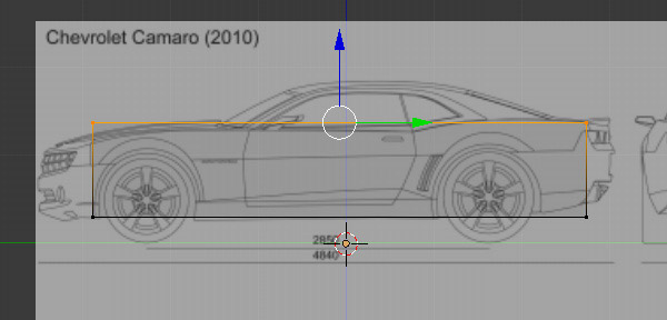
Search for 'Chevrolet Camaro Blueprint' in Google. Choose a set that has all four views of the car- top, front, side and back. I selected this image fromcartype.com. Next, open Blender and in a new file, select all the objects by pressing the A key and then press Delete on the keyboard to delete them.

Step 2
Press N to bring out the Properties panel. Scroll down to the Background Image panel and click on Add Image.

Click Open to browse and select your image. The Background image is only viewable in ortho mode in the left, right, top, bottom, front and back views.

Step 3
Though the image is set for all views (left, right, top, bottom, front and back), we might have to align and move the model every time to match the background image for each different view, again and again. So we must have different image settings for each view.
In the Background Images panel, choose Front in Axis. This means that this image will be viewable only in the front view, the shortcut to which is 1 on the Numpad. Adjust the Opacity slider to your preference.

Step 4
By default the image is displayed at the center of the viewport. But we need to adjust it in such a way that the front view of the car is in the center, as we need only the front part of the car for this view.
With the mouse in 3D view, press 1 on the numpad to get into the Front view. Make sure you are in ortho view mode - press 5 (numpad) to toggle between ortho mode and the perspective view. Adjust the X and Y sliders so that the front view of the car is in the middle of the blue line (X axis) and the bottom of the wheels are touching the red line (Y axis). You can press Shift while dragging the X and Y sliders for precision. The front view setup is now done.

Step 5
With the mouse in 3D view, press 3 on the numpad to get into the Right view. In the Background Image panel, press Add Image.

Click on the Image button and select the same image.

Step 6
Select Right for the Axis option, as we will assign the image only for the Right view.

Adjust the placement with the X and Y sliders in such a way that the bottom of the tires are touching the red line (X axis) in the sideview.

Step 7
Similarly, add another Background image for the Top view. Adjust the X andY sliders so that the top view of the car in the image is in the center. In a photo editor, I have rotated my image 90 degrees so that the top view of the car in the image is vertical. This is not compulsory, but it will be easier to align and match the model to the reference image in the top view, otherwise we might need to move and rotate the model again and again to match the reference.

Step 8
Now add another Background image for the Back view. Press Shift-1 (numpad) to get into the Back view. Adjust the X and Y sliders so that the back view of the car in the image is in the center and the base of the wheels are just on top of the red line (X axis). Now we have set up all the background images for all ortho views. You can check them by pressing the numpad keys - 1 for Front, 3 for Right, 7 for Top and Shift+1 (Numpad) for Back. Press Control-S to save the file.

2. Modeling the Body
Step 1
Press 3 on the Numpad to get into the Right view. Before we start modeling, we need to know which lines to follow. The lines marked in blue are the actual sides of the car, whereas the line in red is not. The red line is the center of the car.

Press 3 on the Numpad to get into the Right view. Press Shift-A and add a Plane.
Step 2
By default the plane is aligned to the grid floor. Press TAB to enter into Edit mode. We need to rotate it 90 degree, so that it is aligned to the right view. With all the vertices selected, press R (to rotate), then N (to enter a numeric value) and then type 90 (for 90 degrees). Finally press Y (to rotate on the Y axis) and press Enter to confirm. You can press T and N to hide the Properties panel and Toolshelf.

Step 3
Press B to drag select the two vertices of the side. Drag them to the side edge of the car, with the arrow widget. You can turn On/Off the widget from the window header.


Similarly, drag the left two vertices to the edge of the car. Press B to drag select the vertices. Drag them to the side edge of the car with the arrow widget.

Step 4
You can toggle between solid shading view and wireframe view with the Z key (so that we can see the reference image.) Drag select the bottom two vertices with the B key and then move them using the arrow widget to align them with the bottom line of the car.

Again, drag the top two vertices to align them with the bottom border of the windows, as shown in the image.
Step 5
Move your mouse over the mesh and press Control-R to create an edge loop and Left Click to confirm. Move your mouse and place it on the edge of the wheel cut. Left Click again to confirm the position.

Step 6
Create another edge loop (Control-R) and place it on the other edge of the wheel cut.

Step 7
Similarly place edge loops on the borders of the front wheel cut, as shown in the image.

Step 8
Add another edge loop, this time horizontal across the body, just above the tip of the wheel cut. Place your mouse over the mesh and press Control-R. Move the mouse near the sides to bring up the horizontal loop cut option, Left Click to confirm. Move the mouse up to place the loop on the top edge of the wheel cut, and Left Click again to confirm the position.

Step 9
Add new edge loops exactly in the middle of both wheels, one by one.

Step 10
Add 2 more edge loops each for the borders of the door. Create and place them one by one.

Step 11
Right Click on the vertex in the center of the wheel, as shown in the image. Press Del to delete it.


Similarly select the middle vertex of the wheel by Right Clicking and then delete it by press the Del key.

Step 12
Right Click on the top corner vertex to select it. Press G on the keyboard and move the point downwards to match the reference line. Left Click to confirm the position.

Move and match all the points one by one, with the side line of the car in the reference image.

Step 13
Again, move the vertices of the wheel cut to give a nice round shape. Don't move them down too much, as we will add more vertices.

Step 14
Add a new edge loop as shown in the image below. Move your mouse over the mesh and press Control-R to add an edge loop. Left Click to confirm and then place it around the bottom. Left Click again to confirm. Move and tweak the outer vertices to give it a nice round shape.

Step 15
Similarly add another edge loop to the front and back parts, and then move the vertices to give it a round shape. Remember to Right Click to select a vertex, and use G to move.

Step 16
Press A to deselect any vertices, and then press B to drag select the top vertices as shown in the image. Press E to extrude them. Move you mouse upward and then Left Click to confirm.

Step 17
Right Click to select a point. Press G and move it to match and align it with the reference. Do the same for each point one by one, as shown in the image.

Step 18
You can add another edge loop and move the top vertices to make the curve smooth. Press Control-R to create an edge loop and Left Click to confirm. Right Click to select the point and use G to move. Match the reference image and then press Control-S to save the file.

Step 19
With the mouse in 3D view, press 1 on the numpad to get into the Front view. Press A to select all the vertices of the mesh. Press G and then X to move it along the X axis towards the side of the car. You can also use the arrow widget to move.

Step 20
With all the vertices selected, press E to extrude the mesh. Move the mouse towards the center of the car and Left Click to confirm.

Step 21
With the new faces selected, press Del to bring out the delete options and select Faces. We will be generating the other side with a modifier, so we don't need the middle faces. Important: Select all the vertices withA and then press Control-N to recalculate the normals of the faces.

Step 22
Press B and drag select the top corner vertices. Make sure you are in wireframe mode (Z key) so that you don't miss any vertices while selecting.

Step 23
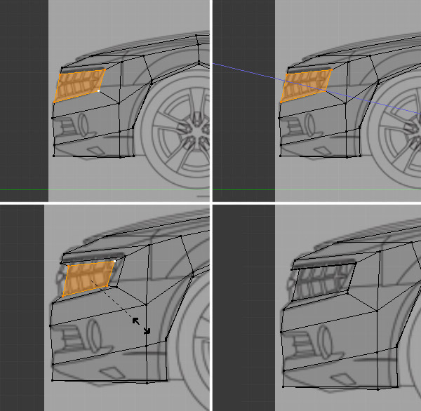
Press A again to deselect any vertices. Now select the vertices covering only the wheel wells, and the body in between, just like in the image. Hold Shift and Right Click on the vertices for a multiple selection. Make sure you don't select any other vertices. If by chance you select any, then Shift-Right click again on that point to deselect it. Press Z to toggle between solid shade view and wireframe view.

Step 24
Press 1 on numpad to get into the Front view. Press G to move the selected vertices towards the side and Left Click to confirm. With the vertices selected, press R to Rotate them to match the side of the car. You can also tweak the individual vertices if needed.

Step 25
In the Properties panel, click on the Modifiers button. Press Add Modifier and select Mirror.

Step 26
We see that the other half is generated by the mirror modifier. In the Modifiers panel press the Editing button and turn Clipping on. Clipping will prevent the center vertices from moving away from the mirror/center. If there is a gap in the center line of vertices, then drag select them with the B key and then move them closer with the G key, or with the arrow widget.

Step 27
Select the four front vertices as shown in the image. Hold Shift and then Right Click on the vertices to select more than one vertex. You can rotate the 3D view by pressing the middle mouse button and moving the mouse. Press 1 on the numpad to get into the side view. Move those selected vertices to match the reference image, using the Arrow widget to move.

Step 28
Similarly, move the center vertices, one by one, to match the reference image.

We see that the car is now taking shape.

Step 29
Press 7 on the numpad to get into the Top view. Again, select and move the vertices one by one to match the reference image.

Press Z to toggle between solid shade view and wireframe mode to see the reference image. Match the vertices to the line of the side window and rear windshield.

3. Modeling the Front
Step 1
Press 3 on the numpad to get into a side view. Press Z to toggle on wireframe mode (if you are in solid shade mode.) Move the vertices to match with the reference as shown in the image. Right Click on a vertex to select it and press G on the keyboard to move. You may also use the arrow widget to move the points.

Step 2
Select the front face by selecting the four vertices.
Press E to Extrude and the Esc key, so that the newly extruded face remains in the same position.
With the new face selected, press S and Scale it down.
Move the vertices to match the front part of the car. Right Click to select and G to move.

Step 3
Select the newly created face by selecting its four vertices. Press and hold Shift to select multiples.
Press E to Extrude it once again. Press the Esc key or Right Click to confirm the position of the new extruded face.
Press S to Scale and move the mouse closer to scale them down.
Move the vertices one by one to match the reference. Right Click to select a vertex and then press G to move.
Step 4
Now tweak the newly formed vertices and face in the Front view as well. Press 1 (numpad) to get into the Front view. Press Z to toggle between solid shade view and wireframe view to see the reference image behind.

Step 5
Also be sure to check the top view as well. Press 7 (numpad) to get into the Top view.

Step 6
With the mouse over the model, press Control-R to add an edge loop across the center as shown in the image. Left Click to confirm the position.

Step 7
Now select the bottom vertices (one by one) and match them with the reference image. Right Click to select, and then press G on the keyboard to move. Press Z key to toggle wireframe mode.

Check and match the shape from the side view as well. Press 3 (Numpad) to get into the side view.

Step 8
In the side view:
Select the four vertices as shown in the image. Hold down Shift and click to select more than one vertex.
Press E to Extrude and without moving the mouse, Left Click to confirm.
With the new face selected, press S and Scale it down a bit and again, Left Click to confirm.
Position the vertices to match the reference image. Right Click to select and G to move any vertex.

Step 9
Press 1 (numpad) to get into the Front view and match the bottom part with the reference image. The front part of the car is now done.

Step 10
As we added another loop in Step 6, we have an opportunity to smooth the curves out a bit. Tweak the vertices to match the reference and to give it a nice round shape and curve.

Check with the reference image also. Press Z to toggle between wireframe mode and solid mode.

4. Tweaking the Back
Step 1
Lets smooth out the awkward dent at the back. Select the two vertices shown in the image. Hold Shift and then Right Click to select multiple vertices. Press W to bring up our specials menu and then select Subdivide.

Step 2
Now select the two adjoining faces by select all 7 vertices, as shown in the image. Press Control-T to triangulate these faces.

Step 3
Right Click on the center point to select it, and press G to move it upwards. You can also use the arrow widget.

Make sure the contour is smooth and be sure to check it from all angles.

Step 4
Now click on Face select mode, so that we can directly select any face with a Right Click, instead of selecting the vertices to select one face.

Step 5
Select the two triangles/faces as shown the image, and press F to make them one face with four vertices, i.e. a quad.

Select these two faces/triangles and press F to make them one face, or a quad.

Again, select these two upper triangles and press F to make them one face.

Press Control-Tab and select Vertex select mode. Tweak the points to give it a nice contour.

Step 6
Press 3 on the numpad to get into the side view. Tweak the vertices to match the reference as shown in this image. Right Click to select any vertex and use G to move.

5. Modeling the Hood
Step 1
Select the front three faces of the bonnet/hood. Press E to Extrude and move your mouse a little bit to give it some height, and then Left Click to confirm.

Step 2
Right Click on the top vertex and then hold Shift and Right Click on the bottom vertex to select both in that order. Press Alt-M to bring out the Merge menu and then select At Last, so that the selected vertices will be merged onto the last selected vertex.

Step 3
Do the same with the center vertices. Select the top one first and then the bottom one. Press Alt-M to bring up the Merge menu and again, select merge At Last.

Step 4
Press 7 on the numpad to get into the Top view. Select the extruded part of the bonnet and move the vertices to match the reference.

Step 5
Now select only the top part of the extruded bonnet. Press G to move it towards the left, matching the reference. Move the vertices one by one and remember, Right Click to select and G to move.

We now have the body ready.

6. Modeling the Wheels
Step 1
Press 1 (numpad) to get into the Front view. Left Click near the center of the wheel to position the 3D cursor there. Press 3 (numpad) and in the side view, Left Click again on the center of the wheel to position the 3D cursor at the center.

Step 2
Press T so that you have the Tool Shelf panel open, press Shift-A and add a Cylinder.

In the Tool Shelf panel (at the bottom), we see many options to tweak the recent command.

Step 3
Check the Align to View box, so that the wheel is facing us (side view).

Step 4
Reduce the Vertices count to 14.
Adjust the Radius slider until the Cylinder matches the size of the wheel on the reference. (you can also adjust it later.)
In the Cap Fill Type option, select Triangle Fan.

Step 5
Press 1 to get into the Front view. Reduce the Depth amount so that the thickness of the cylinder matches the wheel.

Step 6
With the Cylinder selected, press G to move and place it precisely. Use the scroll wheel to zoom in and out, and press S to Scale it. Check from the side view as well.

Step 7
With the Cylinder still selected, press Shift-D to make a duplicate. Left click to confirm the position. And press G to move the new cylinder to its place. You may also use the arrow widget.

Step 8
Adjust, place and scale it to match the reference image. Press G to Move, S to Scale and Control-S to save the file.

Conclusion
The car model is now ready for texture painting, which we will do in second part.

From: http://cgi.tutsplus.com/tutorials/create-a-low-poly-camaro-in-blender-part-1--cms-21730
You must Sign up as a member of Effecthub to view the content.
A PHP Error was encountered
Severity: Notice
Message: Undefined index: HTTP_ACCEPT_LANGUAGE
Filename: helpers/time_helper.php
Line Number: 22
7029 views 2 comments
You must Sign up as a member of Effecthub to join the conversation.