Modeling & Rendering an Interior Scene using 3ds Max and Vray: Part 1
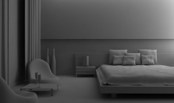
Our recent Stunning Interiors roundup got a lot of people talking about interior rendering tutorials, and today we're happy to bring in Flavius Cristea to discuss his process when creating stunning interior renders using 3Ds Max. From the modeling, through material creation to the final rendering process, this 2-day tutorial is a great insight into the art of Arch-Vis Interiors.
Additional Files/ Plugins:
Step 1
Since we're aiming to make a realistic interior scene, the scale of the objects is very important. To keep things accurate, go to Customize > Units Setup and select the Metric system, and then choose Centimeters from the drop-down. Throughout this tutorial I'll be giving you the values that I used in the scene, however don;t feel you have to match these exactly!

Step 2 - The walls
Go into the Top View and create a rectangle ( Length:540 cm , Width:450 cm) . Right click on the rectangle and go to Convert to > Convert to Editable Spline. While you still have the rectangle ( which is now editable as a spline ) selected, go to your Modifier tab ![]() , go into sub-object mode ( click the small plus sign) and select all 4 splines. Scroll down until you see the Outline button ( it's in the geometry tab from the Editable Spline option). Type -20 and hit enter to add width to the walls.
, go into sub-object mode ( click the small plus sign) and select all 4 splines. Scroll down until you see the Outline button ( it's in the geometry tab from the Editable Spline option). Type -20 and hit enter to add width to the walls.
Tip: this is a very common technique when creating the 2d layout of the walls. Whilst this is a very simple example, if you have a more complex floor plan simply use the line to trace them and then set an Outline equal to the walls' width. The value of -20 and not +20 was used in order to ensure that the outline will be made outwards and not inwards from the initial shape.

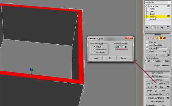
Step 3
Right click on the rectangle, and go to Convert to > Convert to Editable Poly. Now go to polygon sub-object mode by hitting 4 on your keyboard, select all of the polygons and extrude them with a value of 250 cm.
Step 4
Create a box ( L:370 cm , W: 50 cm, H:225 cm ) and move it so that it intersects one of the walls, as seen in the pic below. Now select the walls, and go to Compound objects > Pro Boolean. In the settings rollout, click Pick Operand B and click the box object we just created.

Step 5 - The Floor & Ceiling
Make another box as large as the room (I made mine a bit larger so that I'm sure it intersects the walls - L: 541 cm W:451 cm H:12 cm). This is your floor object. Now make a copy of the box and move it up. You know have a ceiling too!

Step 6 - The Window
Now make another box as large as the one we used in the boolean operation to create the window, but make sure this one has a width of around 5 cm - slightly thinner than the wall itself. Now convert it to an Editable Poly as before.. Select the two large polygons (be careful to select the backside one as well), right click and Inset them with a value of 4 cm. Now delete the two selected polys.
Go into border sub-object mode by pressing 3 on your keyboard, select the two open borders, and click the bridge button to connect them with a loop of polys. Make two chamfered boxes and place them as seen in the picture below to create the divisions in the window frame. Finally, make 3 more boxes with a width of about 0.5 cm and place them into the window frame to form the panes of glass.

Step 7 - Wall Detail
Select the all of the wall polys. Now go into vertex mode and click on the Splice Plane button. Adjust the slice plane and make the cuts as seen in the picture below. To exit the slice plane mode, click on the Slice Plane button once more. Finally select the indicated polygon and extrude it inwards with a value of around 7 cm.
Info: You have made these cuts to create some guide geometry which will be used to add different materials to the walls, and also to place a lamp behind the bed.

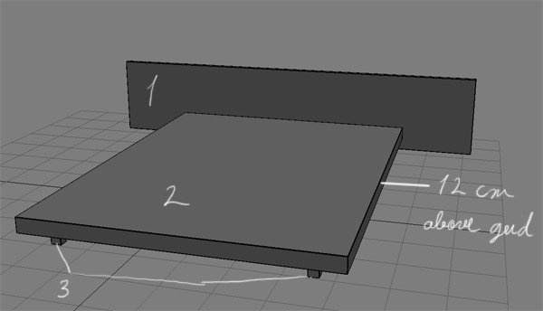
Step 8 -The Bed
The bed is a fairly simple object, with the exception of the blanket - it's really only a set of chamfered boxes. Box1 has these values - L:3.5 cm; W:270 cm; H:55 cm. I then set the Fillet to 0.15 cm and the Fillet Segs:3 to give us some rounded edges.
Box2 had these values - L:220 cm; W:170 cm; H:9 cm; Fillet:0.15 cm and Fillet Segs:3. Finally, Box3 had these values : L:5cm; W:5cm; H:13cm, Fillet:0.15cm and Fillet Segs:3. Place the boxes as seen in the picture below.
Info: Obviously, I didn't just come up with those numbers out of nowhere! I modeled the bed using photo reference, but as I didn't have the actual dimensions I went on the internet, looked for a similar bed and took the exact size only for the main piece (Box 2). The other sections were modeled by simply eye-balling and proportion comparison with the main piece. It's much faster to do it this way than to go in and type in the sizes of every component part. Also, I've used chamfered boxes instead of plain boxes simply because, in the real world, almost nothing has perfect, sharp edges.
Step 9
Now make a chamfered box ( L:205 cm, W:145 cm, H:8.5 cm Fillet:2.4 cm). This is going to be the mattress. You won't add any further details to it as it will be completely covered by the blanket.

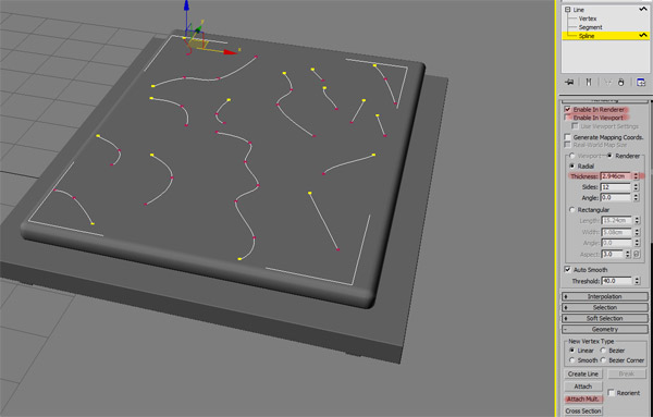
Step 10 - The Blanket Prep
Use the line tool to create some random lines as shown. Attach them all together using the Attach Mult. button, and then click on Enable in Renderer and Enable in Viewport. Set the Thickness to 3cm and then move the lines up so that they sit just on top of the mattress.
Info: In the next few steps you are going to use the Cloth Modifier to quickly and easily create a nice looking blanket. The lines we just created (which are now actually 3d objects) will be used as geometry onto which the cloth will fold.
Step 11 - The Blanket
Create a rectangle (L:225 cm, W:173cm) and place it above the bed. Now go to the Modifier panel and apply the Garment Maker modifier. Set the Density to 0.55
Info: The Garment Maker modifier was used to ensure that there is enough geometry for the cloth to fold. A plane with a lot of segments would have worked also,but sometimes you get better results with Garment.

Step 12
Select the blanket object we just created and add a new Cloth modifier on top. Click on Object Properties in the object panel, select the Rectangle from the List and then turn on the Cloth checkbox. With that done, click the Add Objects button, select all of the elements which make up the bed as shown, and set them to Collision Objects using the checkbox at the bottom of the Object Properties window. With all of that done, click Ok. (Tip: If you select the whole bed and the blanket, press ALT+Q to isolate them, and then add the objects in the cloth modifier list as above, you won't have to manually select them).
Info:In this step we have prepared the cloth modifier for simulation. Since the simulation is pretty basic, the default parameters will work just fine.

Step 13
Select our blanket object, and inside the Cloth modifier options click Simulate Local (once) to begin the simulation. Wait until the cloth falls on the bed, and then stop the simulation by clicking Simulate Local one more time. If something went wrong, or the result doesn't look correct, press the Reset State button to return the simulation back to its initial state. When you're happy with the result, add a Shell modifer on top of the Cloth modifier, and set the Inner Amount to 1cm and the Outer Amount to 0 cm. Finally, add a Turbosmooth modifier with 1 iteration. After you are satisfied with the results, you can delete the 3d lines we created earlier.
Info:Instead of manually modeling the blanket, we have used the Cloth modifier to simulate the folds. The Shell modifier has also been used to give some the blanket some thickness. Due to the fact that we had some very hard-egdes, a Turbosmooth modifier has also been used to soften the edges and smooth the entire object. Don't worry if the polys seem rough in certain areas - later on, we'll be making a material with a displacement map which will fix any smoothing issues. Also, you might need to move the blanket slightly on the Z-axis, so that it touches the wooden part of the bed - in my case just a few cm. Lastly, if you want to manually adjust the shape, you can add a FFD modifier on top, and use the control points to move the folds.

Step 14 - The Bedside
Remember what I said about eye-balling things? The bedside objects are very easy to create - they're really just chamfered boxes. Because of this, I'm only going to give you the dimensions for 1 box and let you to approximate the others. The box indicated in the image has L:20cm, W:45cm, H:12 cm, Fillet 0.45 cm. With that one created, take your time to approximate the others and then move them into position.
Tip: you could also group these parts together, by going to Group > Group and then naming them accordingly.

Step 15 - The Pillows
For the pillows, we start by creating a box (L:30 cm, W:44 cm, H:10 cm) and then we convert it to an Editable Poly. Now go into vertex sub object mode and start to manipulate the verts to create a pillow shape (you can look at a real pillow as well as my wireframes to get an idea of what to aim for!) When you scale, make sure you constrain the proper axis - for example, the Y-axis for the vertices in the green indicated area, and the X-axis for the red indicated area etc.
Tip: Add a Turbosmooth modifier with 2 iterations and turn it on/off to see your progress. Keep moving/scaling vertices and polygons until you get the desired shape. Don't try to be exact, it's not engineering! You want an organic, random shape - not a mechanical one.

Step 16
Now change the Turbosmooth Iterations to 3 (or even 4 if you want some fine details). Then add a Wave modifer on top, and set the Amplitude 1 to 0.125 cm, Amplitude 2 to 0 cm, and the Wave Length to 8 cm. Finally, go into sub-object mode, click on Gizmo and rotate it around 50 degrees.
Tip: Our pillow was too perfect and very, very smooth. The Wave modifier has been added to create some realistic irregularities. You could add another Wave modifier and rotate the gizmo at a different angle, changing the values to obtain a slightly different result. I'd like to point out that all of these values were obtained by trial and error - just move the Amplitude slider up and down and see what it does! If you are unsure about a parameter, press F1 and search for it. Many people overlook Autodesk's reference/help manual but it's probably one of the most valuable things you can have in your arsenal.

Step 17
To finish the bed model, simply make a few copies (Shift+Drag) of the pillow and place them as seen in the picture below. Be sure to change the Wave parameters a bit so you don't end up with completely identical pillows! (You could even add a Noise modifier on top of the Wave one). Now copy the bedside to the other side of the bed. After you are absolutely sure that you won't make any more changes, select everything and convert to Editable Poly. The filesize will now be smaller and 3Ds max will eat less RAM.
Tip: Experiment! Experiment with different values and parametric modifiers - Bend, Taper, Noise, Spherify etc. I'm sure you can get some interesting/realistic results. For example, here I've used the Noise modifier for the smaller pillows.

Step 18 - The Lamp
Create a tube with Radius1 of 6 cm, Radius2 of 5.8 cm, Height of 20 cm, and Sides set to 36. Now create a chamfered Cylinder (judge its size by relating it to the tube) and align it as shown (press ALT+A and click the tube to auto-align). Check that you're happy with the X and Y positions and click Ok.
Info: You couldn't get more basic with modeling in this step :)

Step 19
Go to the front or right view, and using the Line tool, create the shape as seen to the right of our cylinders in the picture below, making sure that you close the spline. Convert it to an Editable Poly, select the polygon and Extrude it with a value of 2.5 cm. Now you have a 3D object but there are no polygons on the back side. To fix this, go into border sub-object mode, select the only open border edge, right click it and select Cap. Now select all edges on the object and Chamfer them with a value of 0.1 cm.

Step 20
Select the last object we created. Click on the Reference Coordinate System drop-down menu, select on Pick and then click the Tube. Now select Use transform coordinate center. Press A to turn on Angular Snap, and rotate the shape 120 degrees on the indicated axis whilst holding Shift to make two copies. Finally, group all of these objects together.
Info: We had to change this object's rotation center to match the centre of the tube, so we modified the Reference Coordonate System using the Tube object as our reference. The rotation angle was 120 because we needed two more copies - three in total - and 3 * 120 degrees = 360 degrees. The other way of achieving this would be to align the object's pivot point to match the tube's pivot, however that way is less flexibile.

Step 21 - The Decorative Vase
You are going to create a 2d shape for the vase. But first, we're going to create a reference object, using the following trick. First make a plane with the height equal to the one your vase and visualize some guidelines (the green lines). Don't try to be exact, again,it's not mechanical accuracy you are looking for. Using the line tool,create a line similar to mine. I've pointed the vertices which are Bezier whilst the others are Corner.

Step 22
Now add a Lathe modifier. Check Weld Core and set the Segments to 32. If your result is not similar to mine, try clicking the Min. button, which will shift the rotation center. On top of the Lathe modifier add a Shell modifier and set the Inner Amount to 0 cm and the Outer Amount to 0.25cm .

Step 23 - The Wine Glass
As with the decorative vase, use the line tool and half trace the contour of the wine glass (shown in yellow here), but this time keep all of the vertices as corners (i.e. bezier with no smooth points). Then add a Lathe modifier with16 Segments, and a Shell modifier with Inner Amount set to 0 cm and the Outer Amount set to 0.6 cm.
Info: This stage is very similar to the lamp creation above, but this time you kept a low poly mesh because later on you'll apply a Turbosmooth modifier. I've used the plane trick (Height:17 cm) again, to ensure that I created the wine glass at the correct scale.

Step 24
This step will be a little bit weird (or maybe just not quite as professional looking) but bear with me! Position the view as seen in the pic below. Add an Edit Poly modifier, and then go into vertex mode and select the the bottom, middle vertex. Now press (and keep pressing) CTRL while you click on the polygon selection mode - 3Ds max will now select only the center polygon.

Step 25
Once you have that bottom poly selected, press on the Grow button (or hit CTRL+PageUp) a few times until the selections expands to match the picture below. Now delete all the selected polygons to leave you with an open border on which you will now right click and choose Cap. Finally, add a Turbosmooth modifier with 2 iterations.
Info: In case you are wondering what exactly this stage is about, our wine glass is now physically correct. If you had skipped Step 24, the light passing through glass would refract in a very strange way, and it would not look right in the final render. The other approach to this would be to trace the whole glass with the line tool,including the inner part, but this approach makes thing a bit difficult when trying to keep the glass the same thickness all the way around, especially if you are not so skilled in using and adjusting splines.

Step 26
Now use the same techniques (create spline, lathe, edit poly to chamfer the edges and turbosmooth) to make the liquid. Make sure that you center it to the glass and scale it up until it intersects the glass sides as seen in the picture.
Tip: The glass has a default material in my pic, but you can currently see through it as it has the See through option checked - hotkey ALT + X with the object selected.

Step 27 - The Armchair
It would be a little weird to explain this step by step because it's really just very simple organic modeling. If I were to say "Extrude that poly 30 cm" etc etc., I would really limit your ability to experiment with the objects in the scene. I've used some very, very basic modeling techniques to produce this object - it's just extruding polygons, and moving/scaling vertices around. The only trick is that after you add the first Turbosmooth modifier, Convert it to an Editable Poly so you can have more vertices to push and pull around. This gives the armchair much more of an organic shape. When you're happy with the shape, add one final Turbosmooth modifier.
Tip: Use your creativity! Your model doesn't have to look exactly like mine. Perhaps get a few reference pictures for inspiration...

Step 28 - The Curtains
Go into your top view and use the line tool to create a staggered line, much like that shown in the image below. Now select all of the vertices, right click and set them from Corner to Smooth.

Step 29
Shift drag the line on the Z-axis to make 2 more copies of it copies of it, and then attach the splines together (look back at step 10 to see how to do this if you can't remember). Now add a CrossSection modifier, and set the Option to Smooth. On top of this, add a Surface modifier and set the Threshold to 1.0 cm.
Info: Some things might go wrong here. Make sure you make the copies of the line in the order I showed you below or the CrossSection modifier will not work properly. This modifier creates a skin across multiple splines, and it works by connecting the vertices of 3D splines together. When adding the Surface modifier, you might need to flip the normals if they are facing the other way around. Also, the Threshold has been set to a lower value so that it won't weld vertices we don't want welded! You can set the Steps to 4 or 5 to smooth out the entire shape.
P.S. - The info above actually comes from Autodesk Help (F1). If you don't understand anything I've written so far, try it out! It's the best reference/help manual I've ever seen.

Step 30
The curtain is ok at the moment, but it's a little too perfect, a little too mechanical. Click the Show End Result button, and go into Line vertex mode. Now convert all vertices from Smooth to Bezier so you'll have much more control. Zoom in (quite a lot), select each independent vertex, and move it around and scale it to change the bezier tangent.

If you move the vertices around at the bottom, you'll notice how the shape changes in realtime.

Tips: This can be quite a long and daunting step but please, take your time. You can move the verts in any direction you want, scale the handles, and perhaps even rotate them. However, notice that while you work with Show End Result, CrossSection and Surface modifier turned on, you won't be able to move more than 1 vertex at a time.
Step 31
Now make a copy of your curtain and then move the verts around on the copy so that you won't have two identical curtains.
Info: As you can probably see, you haven't modeled the top part, where the curtains actually hang on to. That is because we'll position the camera is such way that you won't see that. So, if you can't see it, don't model it!

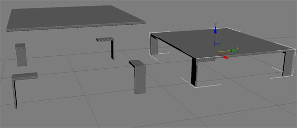
Step 32-The Table
Very basic modeling here. The table top is a chamfered box, and the legs are extruded splines with chamfered edges (see step 19 for an example of this).
<iframe id="google_ads_iframe_/11757429/hub_3d_motion_inarticle_0" name="google_ads_iframe_/11757429/hub_3d_motion_inarticle_0" width="300" height="250" scrolling="no" marginwidth="0" marginheight="0" frameborder="0" src="[removed]"<html><body ></body></html>"" 0px; vertical-align: bottom;"></iframe></p>
<iframe id="google_ads_iframe_/11757429/hub_3d_motion_inarticle_0__hidden__" name="google_ads_iframe_/11757429/hub_3d_motion_inarticle_0__hidden__" width="0" height="0" scrolling="no" marginwidth="0" marginheight="0" frameborder="0" src="[removed]"<html><body ></body></html>"" 0px; vertical-align: bottom; visibility: hidden; display: none;"></iframe></p>
Advertisement
Step 33 - Placing the Objects and the Camera
Now go into your top view and place the objects as seen below. Also, position the V-ray camera using the indicated settings. Don't worry about the rest of the stuff, like f-stop, iso, shutter speed and so on - all of this will be covered in the next part of this tutorial!

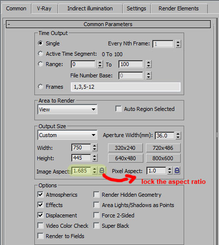
Step 34 - Setting the Aspect Ratio
The image aspect ratio for this shot was almost widescreen (which is actually 16/9=1.777). However I actually chose a value of 1.685, something I came to after making a few test renders, and seeing what I thought looks best for a balanced composition. When you're happy with the aspect ratio, be sure to lock it!
That's it for day 1! I hope you enjoyed it and I'll see you in part two when we add the materials and produce the final render.
You must Sign up as a member of Effecthub to view the content.
A PHP Error was encountered
Severity: Notice
Message: Undefined index: HTTP_ACCEPT_LANGUAGE
Filename: helpers/time_helper.php
Line Number: 22
7249 views 11 comments
You must Sign up as a member of Effecthub to join the conversation.
A PHP Error was encountered
Severity: Notice
Message: Undefined index: HTTP_ACCEPT_LANGUAGE
Filename: helpers/time_helper.php
Line Number: 22
From: http://cgi.tutsplus.com/tutorials/modeling-rendering-an-interior-scene-using-3ds-max-and-vray-part-1--cg-4486